 whatsminer
 2025.08.08
 1K+
1K+ 0
0

Installing and Disassembling Control Board
When indicator lights on a control board are not lit up or when an error code related to the control board is displayed on a main interface of WhatsMinerTool, you can remove the control board and check it. For details about error code and WhatsMinerTool, see WhatsMinerTool_Operation Guide_V2.0_20250311. Before performing this operation, please power off the hydro-cooling miner and take it out from a cabinet.
Disassembling Control Board
Step 1 On the back of a hydro-cooling miner, unscrew 4 screws that secure a control board housing to a hydro-cooling miner housing, and then slowly pull out the control board housing until it cannot be pulled anymore.
Note: M64 series hydro-cooling miner has two control boards, so when disassembling the control boards, it is necessary to remove both front and rear control boards, but there is no requirement for the order.
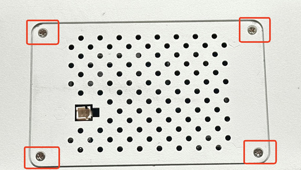
Figure 1-1
Step 2 Disconnect 4 flat cables, and then remove the entire control board housing.

Figure 1-2
Step 3 Unscrew 4 screws that secure a control board to the control board housing, and then remove the control board from the control board housing.
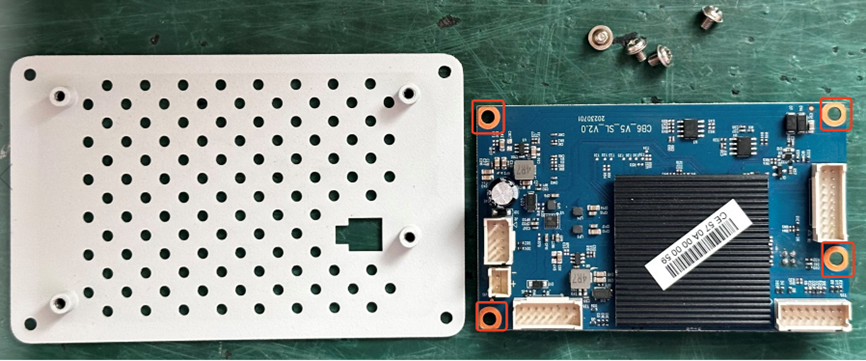
Figure1-3
Step 4 On the front of the hydro-cooling miner, loosen 2 screws that secure a control board housing to a hydro-cooling miner housing, and then slowly pull out the control board housing until it cannot be pulled anymore.
Note: These 2 screws can only be loosened, but cannot be completely removed.
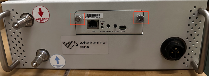
Figure 1-4
Step 5 Disconnect a flat cable from the control board, and then remove the entire control board housing.

Figure 1-5
Step 6 Remove 4 screws that secure the control board to the control board housing, and then remove the control board from the control board housing.
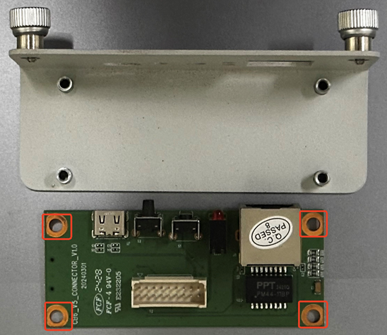
Figure 1-6
Installing Control Board
Step 1 On the front of a hydro-cooling miner, align holes on a control board with those on a control board housing, and then screw in 4 screws and tighten them.
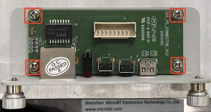
Figure 1-7
Step 2 Insert a flat cable into a corresponding slot on the control board.
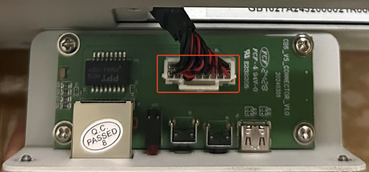
Figure 1-8
Step 3 Screw in 4 screws that secure the control board housing to a hydro-cooling miner housing.
Step 4 On the back of the hydro-cooling miner, align holes on the control board with those on the control board housing, and then screw in 4 screws and tighten them.
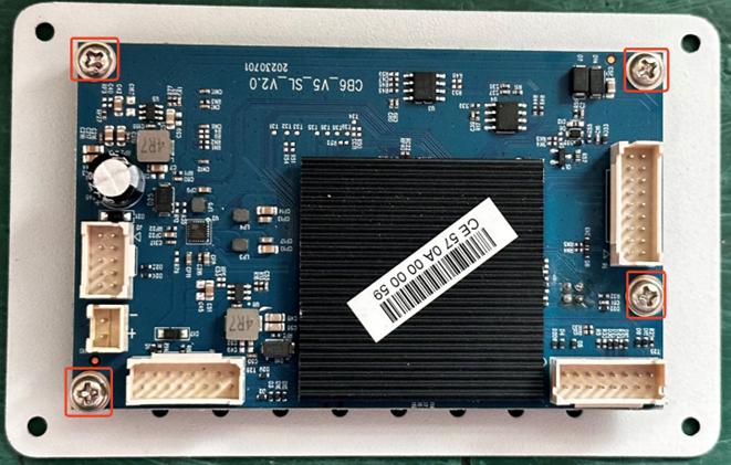
Figure 1-9
Step 5 Insert 4 flat cables into corresponding slots on the control board.
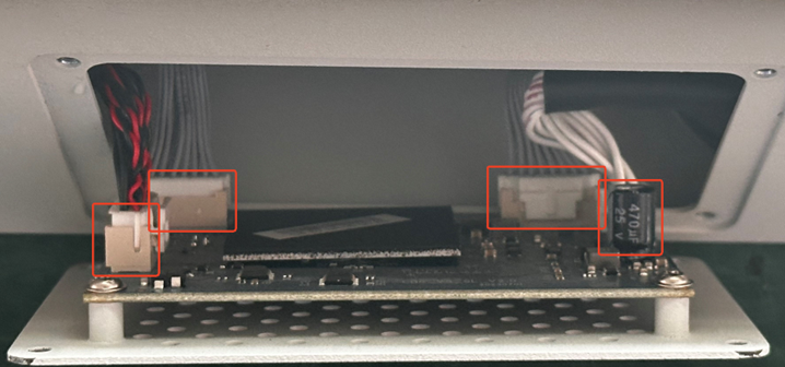
Figure 1-10
Step 6 Screw in four screws that secure the control board housing to the hydro-cooling miner housing, and then tighten them.
 Yes
Yes No
No Feedback
- 1WhatsMinerTool_Operation Guide11K+
- 2WhatsMiner Air Cooling Miner_Operation Guide8K+
- 3WhatsMiner Hydro-Cooling Miner_Operation Guide8K+
- 4WhatsMiner API_User's Manual6K+
- 5 In WhatsMinerTool, there are two error codes about my miner, including 530 Slot 0 not found and 542 Slot 0 reading chip Id error. Could you guide me what should I do?5K+
- 6WhatsMiner Immersion Cooling Miner_Operation Guide5K+
- 7Simple introduction to quick connectors for hydro-cooling miners4K+
- 8WhatsMinerTool: Performance, Power & Remote Functions Q&A4K+
- 9WhatsMinerTool Overclocking Guide3K+
- 10WhatsMiner Hydro-Cooling Series Installation & Removal Guide3K+